
Hardware Intro
Motor Controllers
Section titled “Motor Controllers”While motors are the physical actuators that spin a robot’s mechanisms, motor controllers are the electronic interfaces that control the speed and direction of the motor. Most motor controllers also offer smart abilities like onboard PID controllers and integrated encoders.
Motor controllers are used throughout the robot in many mechanisms:
- Intakes: Spin wheels to collect game pieces
- Shooters: Spin flywheels to launch game pieces
- Indexers: Move game pieces through the robot
- Arms/Elevators: Raise and lower mechanisms (often with position control)
- Climbers: Extend or retract climbing mechanisms
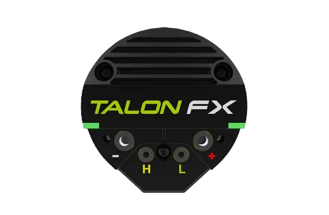
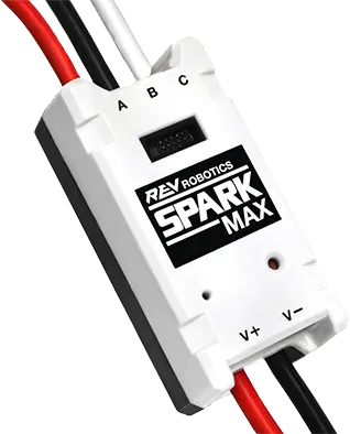
CAN motor controllers are available through vendors such as CTR Electronics (Talon FX) and REV Robotics (SPARK MAX).
Encoders
Section titled “Encoders”Encoders measure rotational motion. They are reliable and less-prone to noise and interference than analog devices (such as potentiometers) because they produce digital signals. They can return the position and velocity of a mechanism. Encoders come in a variety of form factors, and may be mounted at the end of a shaft or have a shaft run through them. Many motor controllers also have integrated encoders. Relative encoders track changes in position and reset to zero when the robot is turned off, while absolute encoders track exact, unique positions across a full rotation and retain this data even when powered off.
Beam Break
Section titled “Beam Break”A beam break detects if anything is between two points and returns a binary value.
Beam breaks are typically DigitalInputs and will return a boolean.
Beam breaks can be used to detect when game pieces pass a specific point on a robot.
Limit Switch
A limit switch detects if something is at a certain position or distance and returns a binary value. Limit switches are often used to restrict the range of motion of a joint or detect the presence of game pieces. While beam breaks and limit switches both detect the presence of an object, they differ in how they do this. Beam breaks detect whether a beam of light is being blocked by an object, while limit switches require physical contact with an object to detect it.
Inertial Measurement Units (IMUs)
Section titled “Inertial Measurement Units (IMUs)”An IMU is a sensor that combines an accelerometer and a gyroscope.
IMUs are used to measure a robot’s orientation, rates of rotation, and acceleration and return these signals as a Rotation2d.
They typically use degrees or radians for angular position (yaw/heading, pitch, and roll) and degrees per second or radians per second for angular velocity.
They can be used for robot heading readings and odometry calculations.
The most popular IMUs in FRC are navX2, Pigeon 2.0, and the onboard SystemCore IMU.
Note that the onboard SystemCore IMU is new for 2027 and has not undergone significant successful testing.
One important thing to note is that gyros measure rate rather than position. Position is inferred by repeatedly measuring the angular velocity and multiplying those values by the delta time between readings. Gyro angle measurements are always relative to some arbitrary zero angle determined by the angle of the gyro either when the robot was turned on or a zeroing method was called. They can have accumulated errors (called “drift”) that increase in magnitude the longer the gyro is used.